If
you are going through this tutorial in order you should already
understand basically what a gate is. Each type of gate turns on to a
special set of conditions. In lesson 1 the focus was centered around
the AND gate, but that is only one type of gate. There are several more
that are used frequently in almost all digital devices (computers,
calculators, digital clocks...)
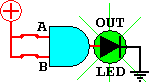
Want to try a simulation for one of these gates? Just click on the symbol above...
**COLOR NOT PART OF STANDARDIZED LOGIC GATE SYMBOL**
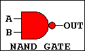
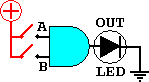
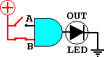
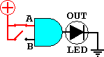
These are the symbols and names for the 8 common logical gates. Each gate has a compliment, meaning it has an anti-gate, or a gate that does the exact opposite. The compliment for the AND gate is the NAND gate (pronounced like it's spelled). Here is a comparison between the AND GATE and the NAND GATE to demonstarte what I mean by opposite.
Notice that based on the given inputs, the NAND GATE responds with the opposite of what an AND GATE would do. The NAND gate only turns on if both input A AND B are NOT high. The NAND GATE symbol differs from that of the AND GATE because of the circle on the output. Any time you see this circle just think of inversion. Whatever goes through this circle gets changed to its compliment. One becomes a zero and a zero becomes a one.
A truth table for the NAND gate compared to one for an AND GATE:
Since the only difference between the AND GATE and the NAND GATE is the inverted output the equation for the NAND gate is almost almost the same. The NAND GATES equation is: A*B = . The line above the "OUT"
represents the compliment. If out equalled a 1 before, it now equals a
0. The line compliments the output (inverts it).
. The line above the "OUT"
represents the compliment. If out equalled a 1 before, it now equals a
0. The line compliments the output (inverts it).
So with the case of lighting LEDs, the LED would only turn off if both inputs were 1, the opposite of the AND GATE.
The truth tables for all of the 8 gates (including the ones already discussed) are below:
Here is a trick to help memorize the truth tables:
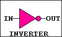
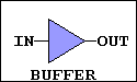
First, the Inverter and Buffer are pretty simple, since they are only 1 input logic gates. The buffer logically does nothing, it just passes the state of its input to the output. Electrically, however, the buffer is important. It can help lower the loads of individual gates. To know more about the electrical workings of gates CLICK HERE.
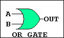
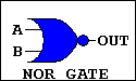
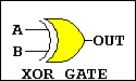
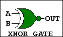
For the remaining six gates, pair them with their compliments. If you remember one, the other is simply the opposite. The OR GATE turns on if A OR B OR Both is high. The NOR GATE is the oppoiste (see truth table). The XOR GATE (Exclusive OR GATE) is similar to the OR gate but excludes the condition of BOTH. It turns on only if A OR B is high, but not both. And, once again, the XNOR GATE is the opposite.
You should know understand what the gates do. Don't worry if you have no idea why any of this matters. In the following lessons we will build simple circuits using combinations of these gates. Then, using those simple circuits, build complex digital devices.
Want to try a simulation for one of these gates? Just click on the symbol above...
**COLOR NOT PART OF STANDARDIZED LOGIC GATE SYMBOL**
These are the symbols and names for the 8 common logical gates. Each gate has a compliment, meaning it has an anti-gate, or a gate that does the exact opposite. The compliment for the AND gate is the NAND gate (pronounced like it's spelled). Here is a comparison between the AND GATE and the NAND GATE to demonstarte what I mean by opposite.
 |
 |
 |
 |
 |
 |
 |
 |
Notice that based on the given inputs, the NAND GATE responds with the opposite of what an AND GATE would do. The NAND gate only turns on if both input A AND B are NOT high. The NAND GATE symbol differs from that of the AND GATE because of the circle on the output. Any time you see this circle just think of inversion. Whatever goes through this circle gets changed to its compliment. One becomes a zero and a zero becomes a one.
A truth table for the NAND gate compared to one for an AND GATE:
| NAND GATE TRUTH TABLE |
AND GATE TRUTH TABLE |
||||||||||||||||||||||||||||||
|
|
Since the only difference between the AND GATE and the NAND GATE is the inverted output the equation for the NAND gate is almost almost the same. The NAND GATES equation is: A*B =
. The line above the "OUT"
represents the compliment. If out equalled a 1 before, it now equals a
0. The line compliments the output (inverts it). So with the case of lighting LEDs, the LED would only turn off if both inputs were 1, the opposite of the AND GATE.
The truth tables for all of the 8 gates (including the ones already discussed) are below:
|
|
|
|
||||||||||||||||||||||||||||||||||||||||||||||||||||||||||||
|
|
|
|
Here is a trick to help memorize the truth tables:
First, the Inverter and Buffer are pretty simple, since they are only 1 input logic gates. The buffer logically does nothing, it just passes the state of its input to the output. Electrically, however, the buffer is important. It can help lower the loads of individual gates. To know more about the electrical workings of gates CLICK HERE.
For the remaining six gates, pair them with their compliments. If you remember one, the other is simply the opposite. The OR GATE turns on if A OR B OR Both is high. The NOR GATE is the oppoiste (see truth table). The XOR GATE (Exclusive OR GATE) is similar to the OR gate but excludes the condition of BOTH. It turns on only if A OR B is high, but not both. And, once again, the XNOR GATE is the opposite.
You should know understand what the gates do. Don't worry if you have no idea why any of this matters. In the following lessons we will build simple circuits using combinations of these gates. Then, using those simple circuits, build complex digital devices.
 |
 |
|
| Gates:
Lesson 1 |
Gates:
Lesson 2 |
Gates: Lesson 3 |