Gate Combinations
It is important to realize that the output of a gate can affect the
input of another. Examine the gate network below and try to figure out
the end result (marked by a "?").
CLICK ON IMAGE ABOVE TO SEE A SIMULATION
CLICK ON IMAGE ABOVE TO SEE A SIMULATION
Starting with the inputs on the
left, we immediately know that C (the output of the blue NOR GATE) is
0. Since the OUTPUT of the NOR GATE is connect to one of the inputs on
the NAND GATE, the value 0 is carried to the input C of the NAND GATE.
The other input on the NAND GATE (D) is connected to input B on the NOR
GATE, which has the value 0. Since the two inputs to the NAND GATE are
0, using the truth table for a NAND GATE, you can figure out the value
of the question mark (?) to be 1. Another way of looking at this
problem would be to break down the gates into what they actually do.
For example, the OR GATE is equivalent to an addition operator (AND is
multiplication). The area of logic design concerned with making these
equations is called boolean algebra.
An Introduction to Boolean Algebra: (NOT NECESSARY FOR UNDERSTANDING THE REMAINDER OF THIS LESSON)
The equation for an OR GATE is OUTPUT=A+B. You may be thinking "What happens if both A and B are 1, wouldn't that mean OUTPUT = 2?" In logical addition (boolean addition), however, 1+1=1. The reason for this is because it is not normal addition. The OR gate "naturally" partly ressembles an additional logic, but you have to remember it is of boolean type (TRUE and FALSE). TRUE+TRUE=TRUE. With the equation we are not trying to model "real" addition, but instead are modeling the OR GATE. The logic for the OR GATE is: IF A OR B OR BOTH are 1 THEN C=1 (The NOR GATE has the exact opposite output). Since both inputs being equal to 1 will still cause an output of 1, the OR GATE is also called the inclusive OR GATE (includes both inputs too). The exlusive OR GATE (XOR GATE), will not output 1 if both inputs are 1. So, for the XOR GATE, 1+1=0. In conclusion, there are two types of additional logic (inclusive and exclusive).
Combinations of gates are really not any more difficult to understand. They only take more time to evaluate (find the result). Lets look at another one, slightly more complicated:
This setup is
identical to the one before, except an AND GATE has been added with
it's inputs connected to the outputs of the NOR GATE and the NAND GATE.
Since the output of the NOR GATE (C) is 1 and the output of the NAND
GATE (F) is 1, the ? equals 1. Remember, this is all determined by the
truth tables of the gates.
One of the more difficult aspects in these kind of problems arise when there is a "loop" in the circuit. For example, consider INVERTER...
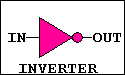
If the input is a 1, the output is a 0 and vice versa. So,
what happens when the output is routed back into the input (shown in
the figure below).One of the more difficult aspects in these kind of problems arise when there is a "loop" in the circuit. For example, consider INVERTER...
As soon as the input receives the
"new" output, the output changes again. This condition is unstable.
Electronically, this oscillation in 1s and 0s will occur at the maximum
speed that the transistors can switch at; Normally around 20 mHz (20
million cycles / second). Just as a side note, if you put an antenna on
this circuit, and tuned a radio receiver to the frequency that the
INVERTER was oscillating at, there would be silience (rather than the
normal static). The electrical noise coming from this loop causes radio
waves!
 With additional components, a
simple circuit like this could be made into a voice transmitter.
With additional components, a
simple circuit like this could be made into a voice transmitter.
Oscillators can also be controlled with addition components to make accurate time sources, such as those used in clocks!
In the next lesson you will learn the names and functions of some gate combinations that, when used together, can make devices like counters.
With additional components, a
simple circuit like this could be made into a voice transmitter.Oscillators can also be controlled with addition components to make accurate time sources, such as those used in clocks!
In the next lesson you will learn the names and functions of some gate combinations that, when used together, can make devices like counters.

