First,
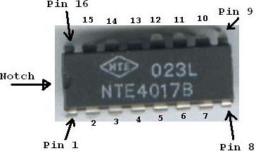
before we begin, it is important to know which pin is which and where
the top of the chip is. The picture above illustrates this. Just about
all inline chips, that is chips with a line of pins on both sides, are
numbered in this manner. To orient yourself, find a notch in the
plastic on the chip or a painted dot. These indicators mark the "top"
of the chip. On the left side, running top to bottom, the pins are
numbered 1,2,3... depending on the size of the chip. The chip pictured
above has 16 pins or 8 on each side. When you number to the bottom,
finish by numbering the rest of the pins on the right side from bottom
to top. That's all there is to it! Sometimes you may find documentation
for a chip you want to use that only mentions the function of each pin,
such as:
--------------------------------
example only: NOT FOR THE 4017B Decade Counter
pin 1: positive power
pin 2: input
pin 3: output
pin 4: ground
---------------------------------
When physically building a circuit with a real chip, rather than in theory on paper, you will have to know the pin numbers. Be sure to check the datasheet of any chip you are unfamiliar with first to prevent possible damage to your circuit or the destruction of your chip.
CAUTION: Some chips are static sensitive and can actually be "blow-out" or destroyed by the static electricity that builds up on you. This can be avoided either by wearing a ground strap, working in a special anti-static workstation, or by avoiding touching the metal pins of the chip.
This
is the schematic representation of the circuit you will soon be
building. It consists only of a single 4017B Decade Counter, 10 LEDs,
and 10 Resistors. (The LEDs are the green circles in the picture above
and the zig-zag lines are the symbolic form of a resistor, the circle
with a "+" in it is the positive end of the power supply, and the 3
lines forming an arrow pointing down is the symbol for ground or
negative end of the power supply/0volts) This circuit takes a clock
input signal through its CLK input pin and "sequences" the output
controlling the 10 LEDs. The effect is something like this:

Need a professionally Designed System?
All Aspects Completely Covered?
We Can Design Anything...
http://www.NovaConceptions.com
(0=led off, 1=led on, left is output 0, right is output 9)
1000000000
0100000000
0010000000
0001000000
0000100000
0000010000
0000001000
0000000100
0000000010
0000000001
1000000000 ; start over! The pattern continuously repeats...
*although the ones and zeros might seem familiar, this output is not normally considered as the binary number system. Click here to see why... BINARY
Don't worry if this schematic looks intimidating. As you can see, many wires (connections/pathways, represented by the black lines) over lap and look very messy. Such a drawing increases the chances of the builder making errors. It is often acceptable for the designer to draw a schematic in a block diagram showing the pin numbers, but not necessarily in the same order as on the actual chip. The following diagram is a block diagram schematic for the same circuit as previously illustrated.
For most
people, this form is much easier to understand and looks cleaner. Pin
numbers are still used to show how to build this circuit on a real chip
as well as a written description of what the specific pin does. For
example, pin 12 is not used (IN THIS CIRCUIT), but it's function is
still defined for clarity.
Now for an explanation of the circuit. Pins 8 and 16 power the chip. The 4017 IC typically can function within a wide variance of voltages (3-16 volts). Be sure to check the datasheet for the exact chip you are using before using 16 volts. Some versions of the 4017 require less power. In this diagram 5 volts was used for the supply. Pin 16 connects to the positive end of the power supply and pin 8 is ground.
The chip also has some configuration pins, which give the user more design options, which will be discussed later in detail. In this circuit the chip has been configured to count from 0-9 in order and then reset. Pin 13 enables the chip (ground=enable and high=disable). Additional circuitry could be used to provide a pause function by temporairly disabling the chip! Pin 15 is also grounded which gives the chip its full range of counting. As soon as pin 15 goes positive (high) the chip resets (output 0 goes high / LED 0 lights up and all other outputs turn off). If this pin were not grounded the chip would not count because it would be always reset. The designer can also use this to create special effects. By connecting the reset pin (pin 15) directly to output 3 (pin 7) the circuit will count like this:
1000000000
0100000000
0010000000
1000000000
0100000000
0010000000
....repeat...
Notice that outputs 3-9 don't even light up! As soon as output 3 goes high, the chip immediately resets. One of the chips own outputs controlled its reset pin to produce a different effect. Can you see how this could be used to build a digital clock??
Pin 12 --- When the counting sequence of the chip is reset this pin temporarily goes high ( for one clock cycle ) This pin can be connected to another 4017 chip to provide a "slower" counter. Each chip can divide the frequency of an incoming clock signal by a factor of 1,2,3,4,5,6,7,8,9, or 10.
Pin 14 is the clock input. When the clock signal goes high the values of the output change. So if the outputs were in this state: (100000000) and a clock signal came along the outputs would change to this state: (010000000). The clock input is very important, it tells the chip when to count and without it the chip would do nothing. Almost all digital devices have some type of clock which provides timing and synchronation.
So, how do you build a clock signal generator? Its easy, really. All it is is a alternating signal (high,low,high,low (1,0,1,0....) ) In principle this could be built using nothing more than a push button switch, where in one position the switch is high and in another the switch is low. However, as I said this can only work in principle. Real switches are plagued by an inheriant property known as contact bounce. At the microscopic level, think of someone fliping a switch or pushing a button. The two metal contacts inside come closer and closer (imagine this in slow-motion). When the contacts impact, the force (although small) causes them to recoil and bounce. Its like dropping a ball, when it hits the gorund it will bouce and then it will be overcome by gravity and hit the ground again, however it will also bouce again. In digital electronics this problem cannot be tolerated because today's electronic circuits are actually fast enough to detect these bounces. So if you were trying to make a counter that counts how make times you pushed a button it would be inaccurate. Every press could generate a different amount of bounces so the system would be unreliable. The problem is solved by a process known as conditioning. Capacitors and latch circuits can be used to provide a "debounced" signal.
Most people, however, would want an automatic clock signal generator, especially for this type of circuit when it would be used in a digital clock or christmas tree chaser lights.

Now its time to build the circuit, in reality...
Now for an explanation of the circuit. Pins 8 and 16 power the chip. The 4017 IC typically can function within a wide variance of voltages (3-16 volts). Be sure to check the datasheet for the exact chip you are using before using 16 volts. Some versions of the 4017 require less power. In this diagram 5 volts was used for the supply. Pin 16 connects to the positive end of the power supply and pin 8 is ground.
The chip also has some configuration pins, which give the user more design options, which will be discussed later in detail. In this circuit the chip has been configured to count from 0-9 in order and then reset. Pin 13 enables the chip (ground=enable and high=disable). Additional circuitry could be used to provide a pause function by temporairly disabling the chip! Pin 15 is also grounded which gives the chip its full range of counting. As soon as pin 15 goes positive (high) the chip resets (output 0 goes high / LED 0 lights up and all other outputs turn off). If this pin were not grounded the chip would not count because it would be always reset. The designer can also use this to create special effects. By connecting the reset pin (pin 15) directly to output 3 (pin 7) the circuit will count like this:
1000000000
0100000000
0010000000
1000000000
0100000000
0010000000
....repeat...
Notice that outputs 3-9 don't even light up! As soon as output 3 goes high, the chip immediately resets. One of the chips own outputs controlled its reset pin to produce a different effect. Can you see how this could be used to build a digital clock??
Pin 12 --- When the counting sequence of the chip is reset this pin temporarily goes high ( for one clock cycle ) This pin can be connected to another 4017 chip to provide a "slower" counter. Each chip can divide the frequency of an incoming clock signal by a factor of 1,2,3,4,5,6,7,8,9, or 10.
Pin 14 is the clock input. When the clock signal goes high the values of the output change. So if the outputs were in this state: (100000000) and a clock signal came along the outputs would change to this state: (010000000). The clock input is very important, it tells the chip when to count and without it the chip would do nothing. Almost all digital devices have some type of clock which provides timing and synchronation.
So, how do you build a clock signal generator? Its easy, really. All it is is a alternating signal (high,low,high,low (1,0,1,0....) ) In principle this could be built using nothing more than a push button switch, where in one position the switch is high and in another the switch is low. However, as I said this can only work in principle. Real switches are plagued by an inheriant property known as contact bounce. At the microscopic level, think of someone fliping a switch or pushing a button. The two metal contacts inside come closer and closer (imagine this in slow-motion). When the contacts impact, the force (although small) causes them to recoil and bounce. Its like dropping a ball, when it hits the gorund it will bouce and then it will be overcome by gravity and hit the ground again, however it will also bouce again. In digital electronics this problem cannot be tolerated because today's electronic circuits are actually fast enough to detect these bounces. So if you were trying to make a counter that counts how make times you pushed a button it would be inaccurate. Every press could generate a different amount of bounces so the system would be unreliable. The problem is solved by a process known as conditioning. Capacitors and latch circuits can be used to provide a "debounced" signal.
Most people, however, would want an automatic clock signal generator, especially for this type of circuit when it would be used in a digital clock or christmas tree chaser lights.
This is the
simplest way of building a clock generator. By attaching a wire between
the output of this "NOT GATE" to the CLK input of the 4017B decade
counter chip you would get a self incrementing circuit. But still,
there is a problem! There is no guaranteed way of knowing how fast it
will count (oscillate). There must be a way, considering people can
build clocks which keep time down to the second for years.
At this point you should realize that a clock generator can be built using virtually any method. It could be a wheel turned by water with a contact on it where it makes conatct with a stationary brush once per revolution. What I'm trying to say is that almost anything can be made to work. CLICK HERE to learn more about making clock generators and even how to make a 1.000000 second signal generator (great for digital time pieces)
At this point you should realize that a clock generator can be built using virtually any method. It could be a wheel turned by water with a contact on it where it makes conatct with a stationary brush once per revolution. What I'm trying to say is that almost anything can be made to work. CLICK HERE to learn more about making clock generators and even how to make a 1.000000 second signal generator (great for digital time pieces)
Now its time to build the circuit, in reality...
 |
||
| 4017:
Sequencers (You are Here) |
Further Projects for the 4017 are under constructions, check back later! |
|
| PROJECT INDEX |
HOME |